LATEST PROJECTS
Capstone Senior Design
Play Me With Sound!
SAE Aero Design | Regular Class
Our senior design team competed in the Regular Class division of the 2017 SAE Aero Design East Competition in Lakeland, FL. The goal was to design a radio-controlled aircraft that could maximize scoring payload while abiding by SAE and FAA regulations. We were limited to a 1000 Watt power draw and were not allowed to use carbon reinforced materials. The payload consisted of passengers (tennis balls) and their luggage (weights). I was in charge of the electrical system, propulsion system, and the performance of the aircraft as well as leading the team during manufacturing and system testing. Out of the 40 teams that competed, we placed 18th overall, lifting 12.9 lbs for two rounds. It is worth noting that none of us had any previous aero experience, and we were also the only biplane in the entire competition.
Below are a few slides illustrating some of the sections of our Capstone project that I directly contributed to. All images are high resolution, so feel free to click and zoom in if necessary.
Takeoff Performance

Displayed are the results of a takeoff program I created in Excel, which uses an Euler analysis to keep track of the forces present on our aircraft during the takeoff run, as well as the distance and speed required to leave the ground.

This is a snippet of the Excel program, with all input parameters in blue. We used this model to quickly simulate various design changes and their effects on the aircraft performance. During flight testing, we verified that the analysis accurately predicts takeoff distance to within .022% error.

Empty weight: 20 lbs. Takeoff weight: 35 lbs. Wing Span: 96 in. Wing Chord: 24 in. Length: 77 in. Fuselage Width: 7.75 in. Takeoff Distance: 70 ft. CG: 6.5 in. Neutral Point: 12 in.
Displayed are the results of a takeoff program I created in Excel, which uses an Euler analysis to keep track of the forces present on our aircraft during the takeoff run, as well as the distance and speed required to leave the ground.
Propulsion Selection

The top figure is a visual representation of the decision matrix below it, which compared ratios of thrust to weight, thrust efficiency, and propulsive efficiency for each propeller-motor combination.

This is a snippet of the Python propeller code I used to calculate theoretical performance parameters of possible propulsion systems.

Once I established a torque curve and a power curve using the prop code and data from the manufacturers, I used a Matlab program to solve the curve equations for each combination's ideal operating point. This is just a snippet of the entire program.
The top figure is a visual representation of the decision matrix below it, which compared ratios of thrust to weight, thrust efficiency, and propulsive efficiency for each propeller-motor combination.
Propulsion Testing
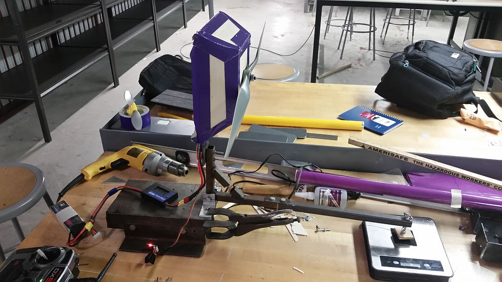
After one failed flight test, I realized that we were likely losing thrust because of the blocking ratio on our nose. I created a mock-up of the original nose and mounted it to the thrust stand for testing, as shown.

After a brief redesign to elongate the nose and improve the blocking ratio, I created another mock-up to test as a comparison. The elongation provided an extra .6 lb of thrust, which was significant for our 22 lb plane.

This was the thrust stand that was designed for propulsion testing. The motor is mounted to an elbow, which is fastened by a hinge to the base. The horizontal arm presses on a digital scale which measures the thrust moment.
After one failed flight test, I realized that we were likely losing thrust because of the blocking ratio on our nose. I created a mock-up of the original nose and mounted it to the thrust stand for testing, as shown.
Electrical System

I created this fault tree to assist in troubleshooting during testing. It allowed us to quickly diagnose possible issues with the aircraft.
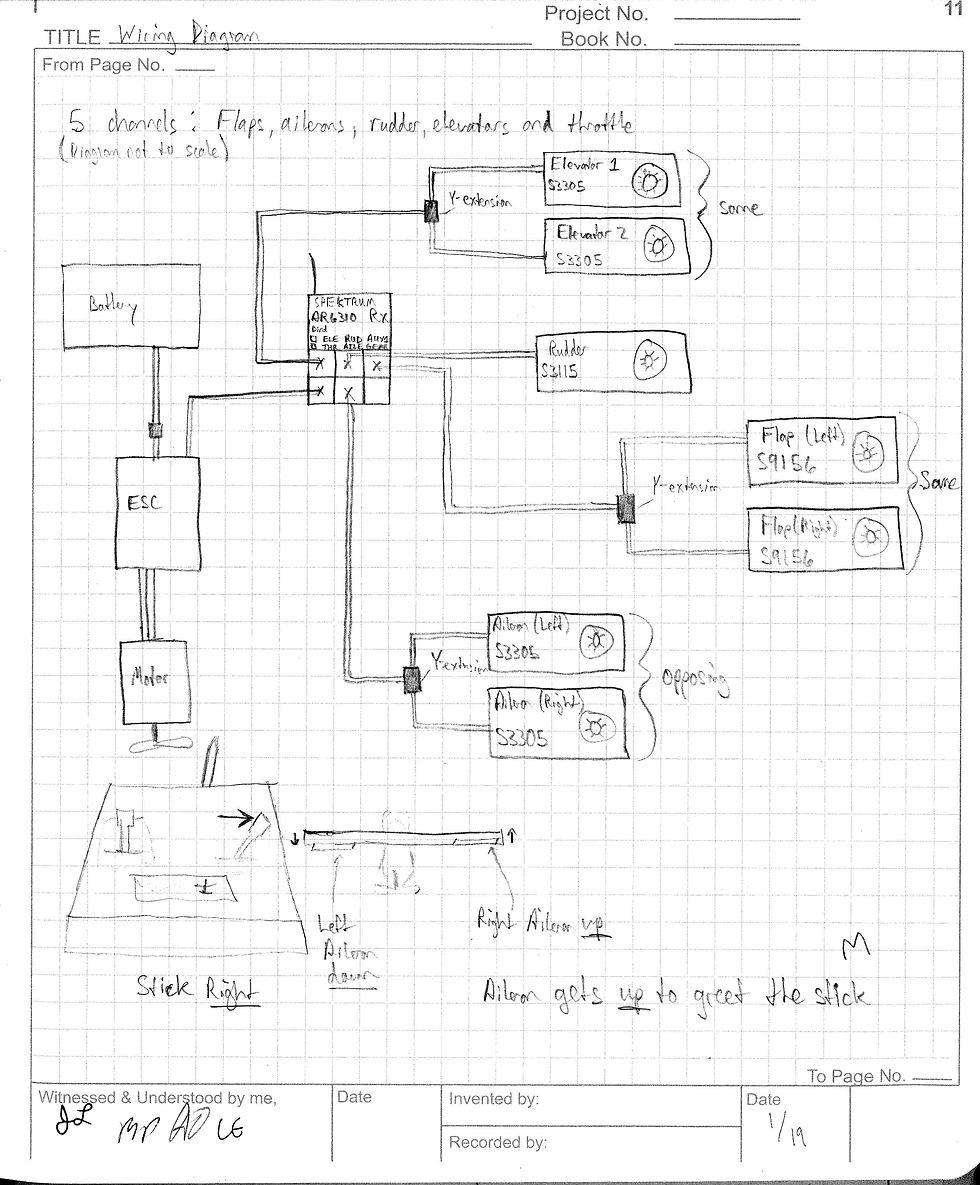
This wiring diagram illustrates the basic inputs and connections that were needed to effectively fly the plane.

This is the arming plug I incorporated into the electrical system as a fail safe mandated by SAE. If the arming plug is not in place, the entire aircraft circuit is incomplete.
I created this fault tree to assist in troubleshooting during testing. It allowed us to quickly diagnose possible issues with the aircraft.